Overview
The algorithm used in the compact banded linear system solvers assumes that the computational grid is decomposed into distributed memory partitions. During the solution process, a pencil of distributed memory partitions is involved. A figure below shows an example of solving the linear system in the vertical dimension, and a pencil of four partitions involved in the linear system is higlighted in red. For numerical schemes that are applied to a periodic domain, the linear systems also contain non-zero cyclic entires. The linear solvers provided in Compack3D support this mathematical structure.
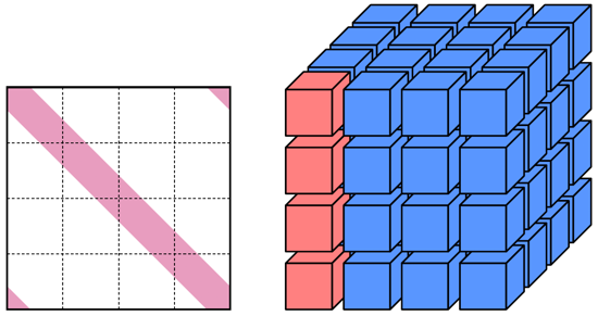
Compact banded linear system formulated across 3D partitioned grid. A pencil of partitions involved in the solution process is highlighted in red.
The algorithm considers hiearchical parallellsms with heterogeneous memory access, and has much lower communication footprint across distributed memory partitions. These designs make the algorithm suitable for computations using multiple GPUs or multi-core CPUs on the modern high-performance computing architectures.
Basic elimination patterns
The basic elimination pattern used in the compack banded linear solvers in Compack3D follows the cyclic reduction (CR) algorithm (Buzbee, Golub, and Nielson, SIAM J., 1970) and its fully parallel variant known as the parapllel cyclic reduction (PCR) algorithm. In each elimination step, the original off-diagonal entries in a row are eliminated by the neigboring rows. For a tridiagonal system, two neighboring rows participate in each elimination process, and for a penta-diagonal system, each elimination step involves four neighboring rows. In general, as the result after each elimination step, the row has the same number of off-diagonal entries but staggered with zero entries. The staggered zero entries indicate that the current row has even or odd decoupling from the original system, i.e., if the current row is an even-number row, it only couples with other even-number rows in the system, and if the current row is an odd-number row, it only couples with other odd-number rows in the system. The schematics of the basic elimination processes for a tridiagonal and penta-diagonal systems are shown in the following figure.
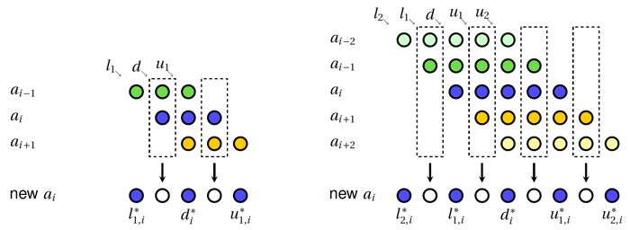
Basic elmination process for tridiagonal systems (left) and penta-diagonal system (right) generalized from the cyclic reduction algorithm (Buzbee, Golub, and Nielson, SIAM J., 1970).
Distributed parallelism
From a view of the entire pencil of distributed memory partitions involved in the linear system, the solution process is equivalent to conducting parallel block Gaussian elimination, as shown in the figure below. As the outcome of the block Gaussian elimination, a block upper triangular system is obtained. The last diagonal block is an independent small block tridiagonal formulated across distributed memory partitions, known as the reduced system. Once the reduced system is solved, the remaining systems can be then solved in parallel within each distributed memory partition. The reduced system is solved using the block PCR across the distributed memory partitions, and other diagonal blocks are solved using PCR with shared-memory parallelism.
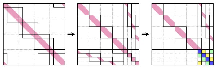
Solution process viewing from distributed memory partitions analogous to parallel block Gaussian elimination: (left) original system with further logical partitions, (middle) logical collumn and row permutations, and (right) resulting structure after block Gaussian elimination. The reduced system is formulated across distributed memory partitions as the last diagonal block.
The reduced system is block tridiagonal formulated across the distributed memory partitions. The block size is equal to the number of off-diagonal entries on each side. The total size of the reduced system is equal to the number of the distributed-memory partitions participated in the solution process. The non-zero cyclic entry blocks exist in the reduced system if the original system is also cyclic. Traditional PCR approach naturally solves a cyclic system of a power-of-two size or a non-cyclic system. If a reduced system is cyclic and whose size is not a power-of-two, Compack3D applies the method of attaching and reattaching to avoid extra communication or non-parallelizable steps in the traiditional methods. A schematic of the solution process for an 11-by-11 cyclic reduced system is shown in the figure blow.
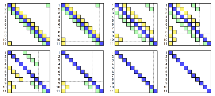
An example of solving a 11x11 reduced system using parallel cyclic reduction with the method of detaching and reattaching.
Related publications
Song, H., Matsuno, K. V., West, J. R., Subramaniam, A., Ghate, A. S., & Lele, S. K. (2022). Scalable parallel linear solver for compact banded systems on heterogeneous architectures . Journal of Computational Physics, 468, 111443.
Song, H., Matsuno, K. V., West, J. R., Subramaniam, A, Ghate, A.S., & Lele, S.K. (2024) Scalable parallel linear solver for compact banded systems . In NASA Advanced Modeling and Simulation (AMS) Seminars.